Global System is a Protocol which is developed by the European Telecommunication Standard Institute(ETSI) to describe the II-Generation digital cellular devices. After a successful test in Finland. It is deployed to replace the Analog Communication (I-G) to the digital communication (II-G). Over 90% of mobile communication uses the GSM protocol to communicate and transfer the data.
GSM Module
GSM module is a mobile communication modem, GSM is an open and digital cellular technology used for transmitting mobile voice and data services operates at the 850 MHz, 900 MHz, 1800 MHz and 1900 MHz frequency bands. In India the network providers almost provide in the frequency of 900 MHz.
GSM MODEM
AT Commands
AT commands which is traditionally called as ATtention commands which is used to communicate with the data transferring modules (Say: WiFi, Bluetooth, XBee, and of course GSM). It uses the two wire serial communication protocol.
Modes of Communication
There an two modes to communicate with the devices with the AT commands.
- With Controller Board
- Without Controller Board
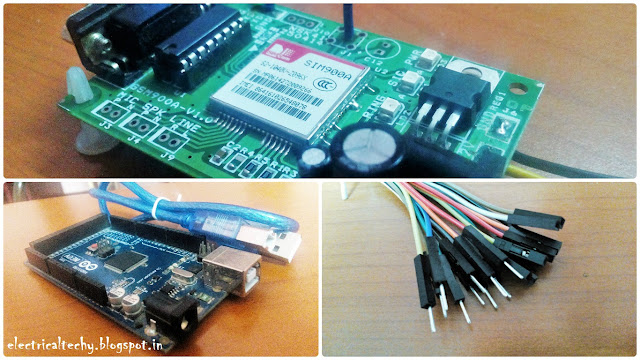
Hardware Required
- Arduino IDE Download Here
Arduino IDE
GSM Setup
GSM module should be set up properly with the Valid SIM card. After locked up, fire up your GSM. The green LED indicates the power. The continues blink of SIG LED denotes that it is ready to capture the signal. After a mean time (Say: 60 Seconds), SIG LED blinks continuously in the rate of 3 Seconds, it denotes that it established the connection to the satellite.
SIM Lock
Troubleshooting
If the 3 seconds blink is not appeared, check the mentioned things
- The Voltage (12V) and Current (1A) rating of your Adapter
- Use only the Valid SIM card
- The Antenna wire in the GSM module (Extend it)
After all set, as the initial test. Call the number in the GSM module from your phone. The RING LED glows as the indication of perfect working of GSM.
All Set
Pin Connection
Wiring between the Arduino and the GSM module should be done to establish the communication. GSM module should be powered separately by 12/1 (V/A) adapter. The 3 wire configuration is used to communicate the PC with GSM.
- RX-11
- TX-10
- GND-GND
Pin Connection
Programming
After completing the task in the hardware section, now it's time to coding. Just copy paste the code to complete the task. Paste it in the Arduino IDE. Chose your Arduino board and select the proper COM port and upload the code. After this open your serial monitor and communicate with GSM.
Serial Monitor
There are several set of AT commands are available. Ubinetics have them, i shared it for you. That's all for today. Hope you enjoyed it.
Thank you
Got Hit by issue ? Feel free to drop mail


No comments:
Post a Comment