Friday, 29 December 2017

MPU6050 | Live graph | Raspberry Pi

Howdy! It's my pleasure to share my another work from my desk. Today I'm going to talk about interesting and important sensor. It's nothing but MPU6050 the combination of Accelerometer + Gyroscope + Temperature in a single board. It basically works with I2C protocol.

Now, what we're going to do is interfacing MPU6050 with the Raspberry Pi and collect the real time data. And we're going to visualize the change in axis in the graph.

Let's get started ๐Ÿ’ช

I've connected my MPU6050 and RPi with the hookups as mentioned. For visualizing the data I used python in combination with matplotlib.

Working GIF ๐Ÿ˜‰


Working Model

It have lot of application. I look forward to hear it from you people.

Thursday, 19 October 2017

Motion Detection | OpenCV | Raspberry pi | Telegram

Surveillance system is an important thing when it comes to protect our properties form the Intruders๐Ÿ‘€. Here is an simple project which can able to protect your belongings form the intruder. Let get started.๐Ÿ’ช

First of, we need a camera and the DVR setup. But thankfully Raspberry Pi in combination with the OpenCV does the job for us. I used the motion detection technique provided by Mr. Adrian Rosebrock from pyimagesearch.com to fulfill my requirement. 

To get the notification when the Intruder is detected. We should push the data to cloud and retrieve it form the location uploaded. It's a long process and took time to build an universal application. So I used a commonly used messaging application called telegram and it's an cross platform application.

Voila! The wait is done. Once I run the program, It capture the motion and send the real time image to mobile phone.

Snaps

Working Snaps

Telegram Message

PoC

Hope this concept will embed into the existing DVR's. Bye for now.

Friday, 13 October 2017

Object detection | Raspberry Pi | Machine Learning | Visually Challenged

      Hello All ๐Ÿ˜Š. After working with the Face to Voice for visually challenged and tried to make it as a product. But a question arises inside me.✋. Recognizing a human is fine. But what if other objects come around them?๐Ÿ˜…. Simple, they ask the person near around them? Yuk! That's not going to happen when the world have a electronics hobbyist like me. So that I've created a system which can differentiate the object in real time and most importantly it should be portable.

      As always Raspberry Pi is a heart of the system with the Raspbian Jessie is used. Thank to Google tensor-flow API which is a open source library for Machine Learning, they've COCO - Common Object in Context. Lots of models set are available in the tensor-flow. I just utilized a basic model sdd_mobileclient_v1, for testing it out the performance. And I just wondered with it's speed๐Ÿ˜ญ. Further, I'm working on to make it as a perfect product.

Working Images:
Pretty Good!

I'll work on to improve the speed of processing on raspberry pi and embedding a audio out to it. Bye for now!✌


Monday, 22 May 2017

Face to voice | Visually Impaired | Raspberry Pi

Howdy! Today I came with an interesting and innovative project which is an boon project for visually impaired (VI) people. It increases the life quality of the VI people in an affordable price. I hope this project will convert into product in future.

After active working of 75+ Hrs with several prototypes finally the success is achieved with Pi Camera and Raspberry Pi

It have three different phases, to detect the face and convert it to voice.
  • Face capture and save as data to the raspberry pi
  • Training generator for the data set
  • Finally live streaming is compared to saved data

Working Prototype

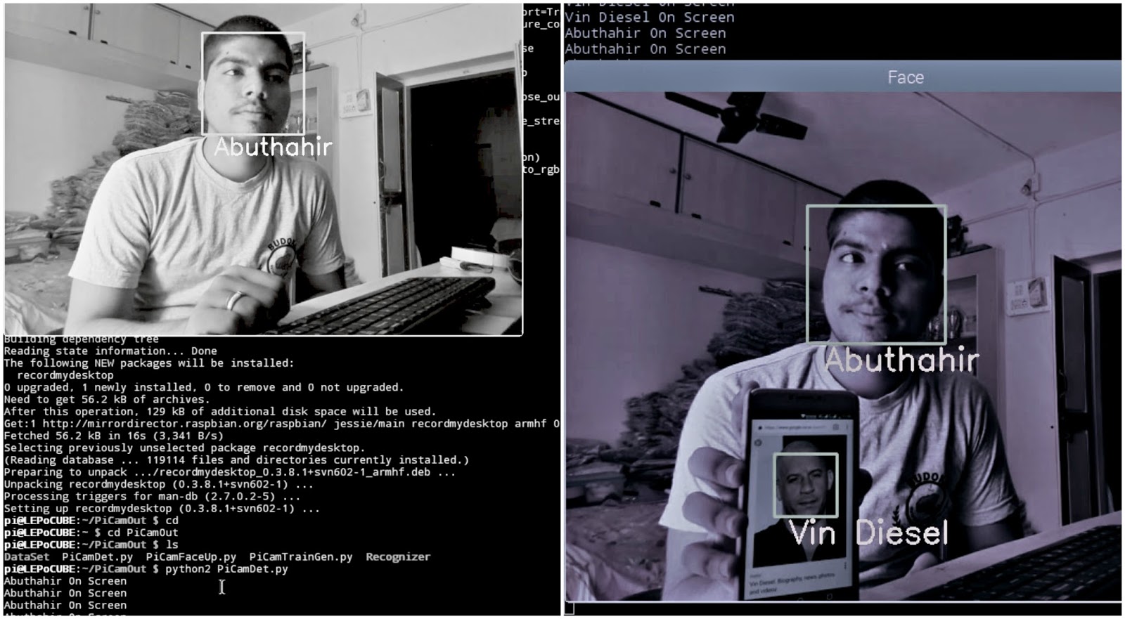
As discussed earlier, it uses raspberry pi and pi camera for the face recognition and if the match found with the faces it give the voice the VI person.

Hardware Snap

Hardware Snap

While concentrating on the hardware it's too simple. Only a R-PI and Pi-Camera. It includes the headphones for voice.

PoC Snap

Working Snap

This written code have a capability to detect the multi-face in a time and gives the name of the person as voice output.

Click for Video

Don't forget to raise your Thumb's Up

Thursday, 4 May 2017

GUI Controlled Devices | Raspberry Pi | Python

Howdy! Today I showed with some exciting model. The prototype which is used to control the connected devices using the GUI window using python and raspberry pi. Before moving to it, know the prerequisites.

Hardware Required
Software Required
  • Python
Software

Python is an pre-installed application in raspberry pi. The package Tkinter is used for GUI creation.

Circuit Schematic


Schematic Diagram

Connect the components as shown in the circuit. If everything gone good. You're almost done.

Coding

If you're really interested in doing this project please click for code. Pull request and Enjoy.

Time to show

You're right. I'm going to show my working model via video.

Click Here

I think you loved it. Meet you again with new concept.

Thank you

Don't forget to raise your Thumb's Up


Sunday, 12 March 2017

Motion Detection | GUI | Raspberry Pi

Howdy! Today we are going to build something weird. This system shows the animated alerts when the intruders enters into your secured area. With the help of Raspberry Pi and Python we are going to build it.

Before we steping into it.You should know the necessity of the first boot of Raspberry Pi and it's an enhanced version of Human Detector.

Hardware Required

Hardware

Software Required

As mentioned earlier, we are going to use Python to finish the Job. Your installed version of raspbian contains the python. If not you can install it by copy paste the code in terminal

sudo apt-get install python3 


Python

Let's do Wiring๐Ÿ˜„

Simply connect your PIR with your Raspberry Pi as shown in the schematic

Schematic Diagram

Time to code๐Ÿ‘Š

I made it easy for you guys. Just copy and paste the code in your python editor window and Run (F5) your code.

Scripting Window

GUI๐Ÿ’–

When the intruder is detected, the  python script is designed to open up an Animated GIF to indicate the interruption in the Security to the user. Working video model is shown below.

Model

Thank you

Don't forget to raise your thumb's up

Hit by a issue, feel free to drop mail

Sunday, 18 December 2016

Lamp Sequencer | LM393 | Arduino

          Howdy, today we are going to do the Lamp Sequencer project which takes sound as input and respond to it. It's easy, funny and lovely. Let's get started.

Hardware Required

Arduino IDE

Wiring Diagram

Let connect the peripherals as described in the table below
Pin outs
Note: If you are using 5V relay, the above pin out is acceptable. If you are using (12 or 24)V relay, Use separate (12 or 24)V DC supply and do common ground.

Looks sick ๐Ÿ˜Š

Schematic

Let's code ๐Ÿ’ช

          Uff.. It's time to code our controller board. This is pretty long here due to sequence switching. But don't worry. Copy paste the code in your Arduino IDE. After done it, compile check and upload the program. Ensure you have selected the specified board and port.

IDE-Code

Prototype GIF

GIF

Thank you
Issues, suggestions, complaints: Drop mail

Wednesday, 7 December 2016

Security System #02 | SW-420 | Arduino | GSM

          Howdy. Today I came up with the another method of Security System which detects the vibration and sends the Alert through message and Even do calls. Check out the #01 of my Security System. Alright, let's do this. Before begin the work you might need to configure your GSM.

Hardware Requirement

Arduino IDE

Let's do Wiring

          To communicate with the sensor and to trigger the GSM at the right time. We need the do the wiring connections as shown in the Fig.

Schematic

Coding time

          Alright. It's time to control the body by it's soul. Copy paste the Code in your Arduino IDE, compile and upload the code. Make sure you have selected the right port and the board.

Code Upload

Working of Prototype

I believe in pictorials rather than words. So here I shown the working pictorial


Thank you

Suggestions, quires, complaints? Drop mail

Tuesday, 6 December 2016

Real Time Sensor Data | Email | Raspberry-Pi

          Raspberry Pi is an single chip tiny computer board which comes up with the several internal features. It's been used for several purposes. Today I came up with the Idea of Sending the Real Time Sensor Data via Gmail. Work begins... Before jumping into it. Setting up of your pi is important

Hardware Required

Required Items

Software Required

  • Python Interpreter   (No need any Special Download. Built-in with Raspbian)

Pi - Python

Wiring to Sensor

          As mentioned earlier I used HC-SR04 Ultrasonics sensor to read it's data. The connection between the sensor and the R-pi is shown.

Pin Connections

 Coding Time...

          We are going to write the code in Python. Make sure you have an updated version of python in your jessie of your R-pi. If you don't have, do this

sudo apt-get update

sudo apt-get upgrade

sudo apt-get install python3

after this is done, just copy the code and paste in your python Editor window not in Interpreter window. Save the file.

Note: For the sender's mail, the less security app should be allowed in the Gmail to access it through Python

Coding

          After this, the code is complied and Runned by either simply pressing F5 or from the Terminal window of your R-pi. Save the file in the home directory so that we can run from multiple windows.

Running From Terminal

python filename.py

Terminal Run code

Received Mail

          Wow... Worked. Here we go.. I got a mail from the Sensor.

Mail

Prototype

          The below shown is my prototype. If you develop one. Share your prototype design also in the comment below.

Prototype

Thank you

Suggestions, quires, complaints? Feel free to drop mail

Friday, 2 December 2016

Security System #01 | HC-SR501 | Arduino | GSM

         Security System is the degree of resistance, to other to access our belongings. Today I came with the Intelligent Security System which makes alert when the Intruder enters in your home or Industry. Let's make it.

Hardware Required

Hardware

Software Required

Arduino IDE

Work begins...

          Before entering into building the prototype, GSM module should be set up in a way to transmit and receive the signal.  To set it up, click here

          After setting up your GSM module. Remove all the previous connection and make the new connection as shown figure.


Circuit Connections

Time to code

            After all done, Just copy and paste the code to your Arduino IDE. Check for proper board and port selection. Compile your code and upload it. While uploading your code disconnect the TX and RX. After successful upload of your code connect TX and RX and press the RESET button once.

Coding Window

Deployment

         Eventually you made it. It's an security system to protect your belongings from the III person.

Deployment of our Design

Human Trace

           When sensor detects the human trace. Immediately generates the Alert message and after a minute. It generates the Call.

Alert Signal


Thank you

Don't forget to raise your Thumb's Up

Got hit by Issue, feel free to drop mail

Wednesday, 30 November 2016

Global Systems (GSM) AT Commands

       Global System is a Protocol which is developed by the European Telecommunication Standard Institute(ETSI) to describe the II-Generation digital cellular devices. After a successful test in Finland. It is deployed to replace the Analog Communication (I-G) to the digital communication (II-G). Over 90% of mobile communication uses the GSM protocol to communicate and transfer the data.

GSM Module

              GSM module is a mobile communication modem, GSM is an open and digital cellular technology used for transmitting mobile voice and data services operates at the 850 MHz, 900 MHz, 1800 MHz and 1900 MHz frequency bands. In India the network providers almost provide in the frequency of 900 MHz.


GSM MODEM

AT Commands

               AT commands which is traditionally called as ATtention commands which is used to communicate with the data transferring modules (Say: WiFi, Bluetooth, XBee, and of course GSM). It uses the two wire serial communication protocol.

Modes of Communication

 There an two modes to communicate with the devices with the AT commands.
  • With Controller Board
  • Without Controller Board
Now we are communicating with the Controller board technique.

Hardware Required

Hardware

Software Required

Arduino IDE

GSM Setup

                   GSM module should be set up properly with the Valid SIM card. After locked up, fire up your GSM. The green LED indicates the power. The continues blink of SIG LED denotes that it is ready to capture the signal. After a mean time (Say: 60 Seconds), SIG LED blinks continuously in the rate of 3 Seconds, it denotes that it established the connection to the satellite.

SIM Lock


Troubleshooting 

If the 3 seconds blink is not appeared, check the mentioned things
  • The Voltage (12V) and Current (1A) rating of your Adapter
  • Use only the Valid SIM card
  • The Antenna wire in the GSM module (Extend it)
  After all set, as the initial test. Call the number in the GSM module from your phone. The RING LED glows as the indication of perfect working of GSM.

All Set

Pin Connection

Wiring between the Arduino and the GSM module should be done to establish the communication. GSM module should be powered separately by 12/1 (V/A) adapter. The 3 wire configuration is used to communicate the PC with GSM.
  • RX-11
  • TX-10
  • GND-GND

Pin Connection

Programming

             After completing the task in the hardware section, now it's time to coding. Just copy paste the code to complete the task. Paste it in the Arduino IDE. Chose your Arduino board and select the proper COM port and upload the code. After this open your serial monitor and communicate with GSM.

Serial Monitor
There are several set of AT commands are available. Ubinetics have them, i shared it for you. That's all for today. Hope you enjoyed it.

Thank you

Got Hit by issue ? Feel free to drop mail

Friday, 17 June 2016

Remote Obstacle Finder | Raspberry-Pi.

            Obstacle detection is an important aspect in an Automotive and Automobile System. The basic obstacle detection is already done. Check here. Now, moving on to the next level. The detection and the range of the obstacle is identified remotely. Let us see how it works.

Hardware Required
  1. Raspberry-Pi ( Refer the first booting of pi here )
  2. HC-SR04 (Ultrasonic Module)
  3. WiFi Adapter (If R-pi2 is used)
  4. LED
  5. Hookups
  6. Protoboard

List of Hardware 


Software Required
      
          After booting up your Raspberry pi with Raspbian. The application software which is required to run the program is Python. Python is pre-installed in OS. If you did'n have it do the following. Open Terminal Window and type the following...
  • sudo apt-get update
  • sudo apt-get upgrade
  • sudo apt-get install python3-picamera
After setting up your Raspberry pi. Move to the Wiring of sensor and Pi.

Wiring Method 

         Connect the Sensor LED and the R-pi with the help of Hookups and protoboard as shown. 

Circuit Schematic

            After finishing the wiring. This body has to be soul with the help of python programming. The soul helps the body to work perfectly.

Being Soul the Body
         
              Python is an most effective and reusable programming which is having an advanced features than other languages.

Python (Editor & Execution Window)

            I make it easy for you. Just copy and paste the code in Editor window form here. Run the code to test it with the help of F5 key.

Remote Access
       
           Here is the best part of the project. The remote access of the system. You could access and run your program from PC, Smart phone or Tablet. All you need to do is connect your R-pi and your control device (PC, Smartphone or Tablet) in a same network with the help of WiFi Adapter.

For Android : Mobile SSH

For PC         : PuTTY

For Window's phone : SSH

For iOS : SSH

          Download and Install the compatible app for your device and connect your device as the same IP of your R-pi.

Here I showed example for Android Devices.

                                                                    Check your R-pi IP address

R-pi Window

Android device connection Method

Steps to be followed

Login with your own user name and password. Once the connection is established successfully, we need to run the python program which is already located in the system. For that type


python yourfilename.py


Execution of Program

Hardware Output


Feel free to post your doubts and questions

Ping me @ Abu Taj